Finding Roof Loading On A Truss At Joints Chegg
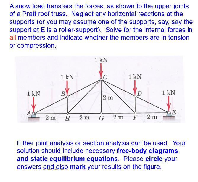
Point loads f1 and f2 applied at joint 1 2 and 3 represent the permanent and imposed loads on the truss respectively where the imposed load is occupancy live load.
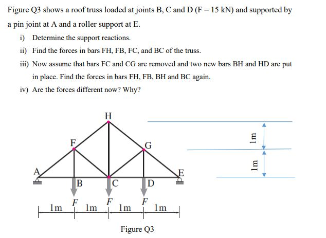
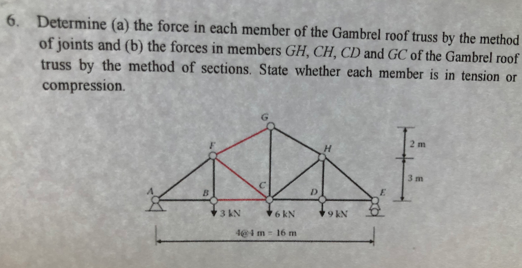
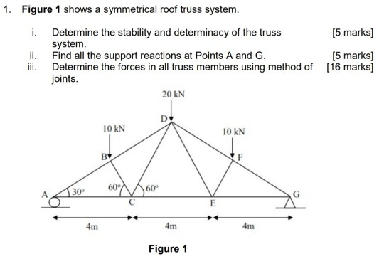
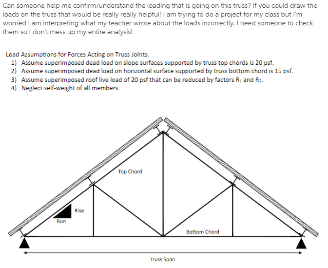
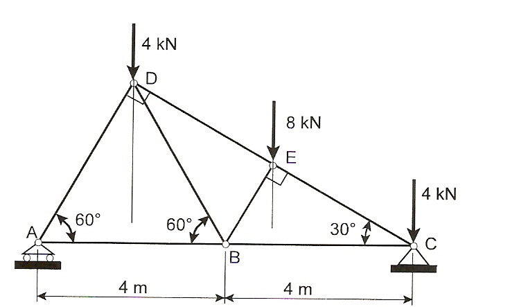
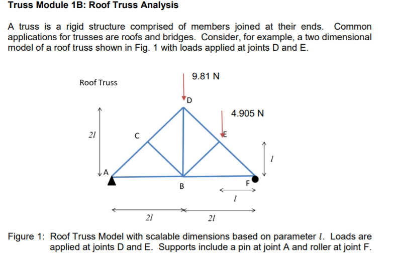
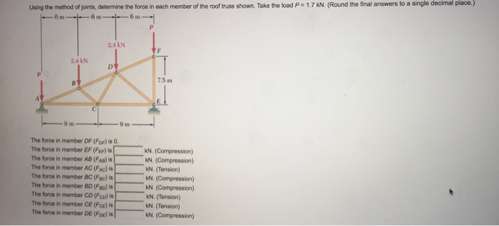
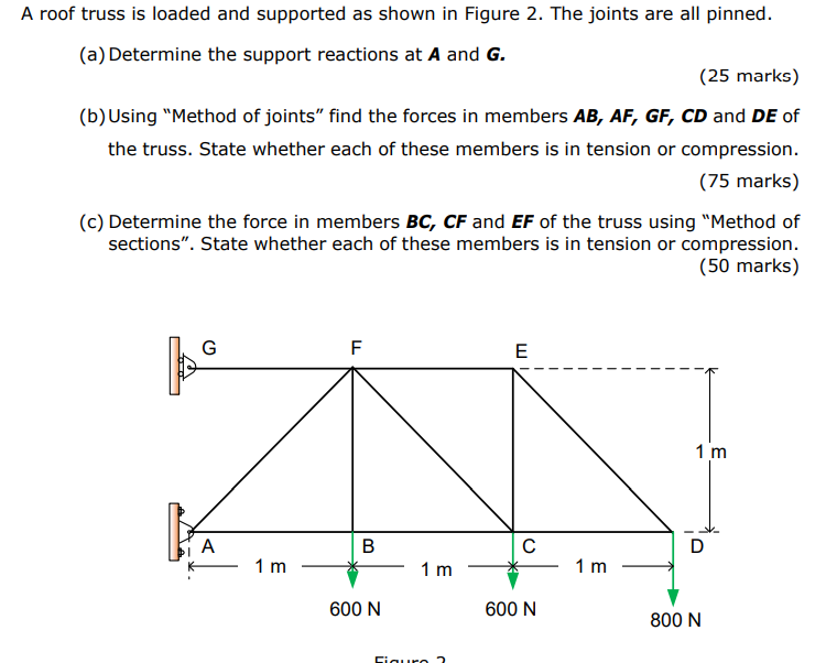
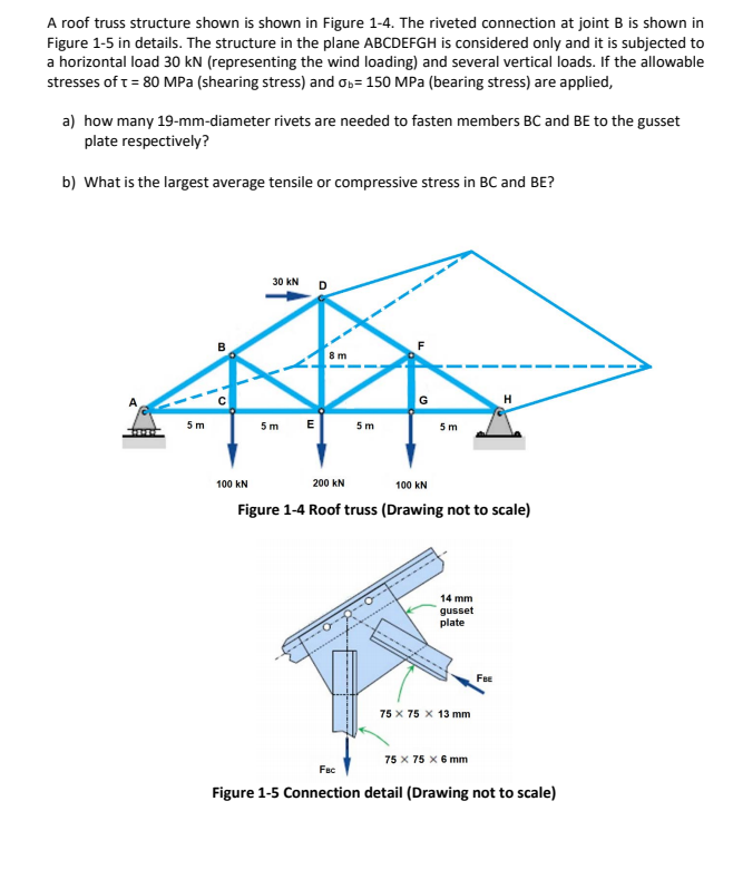
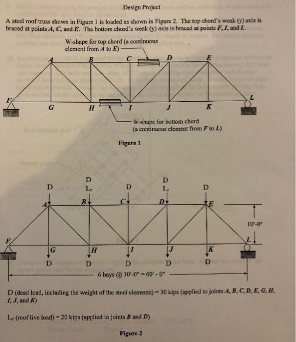
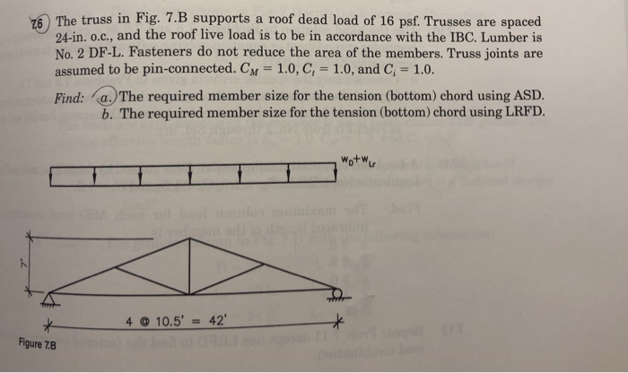
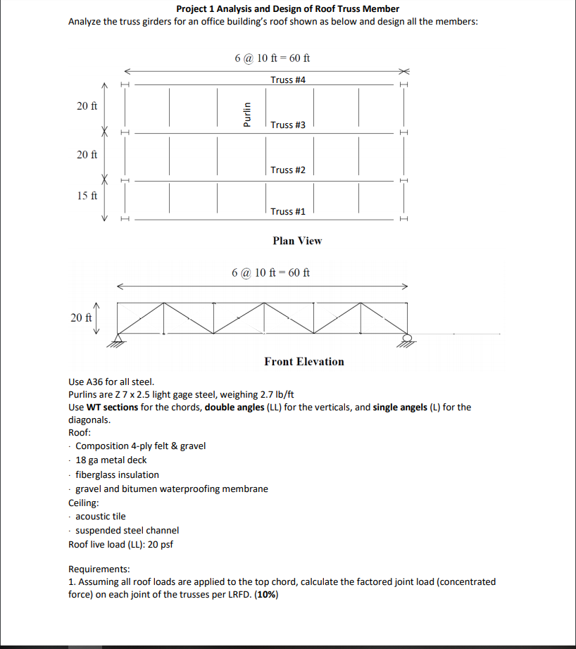
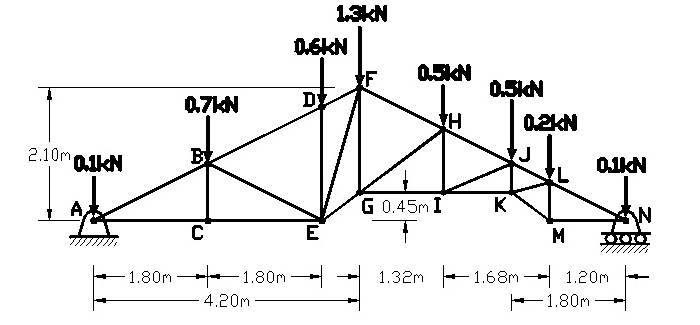
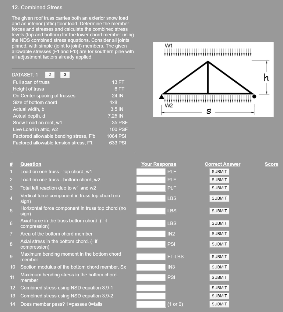
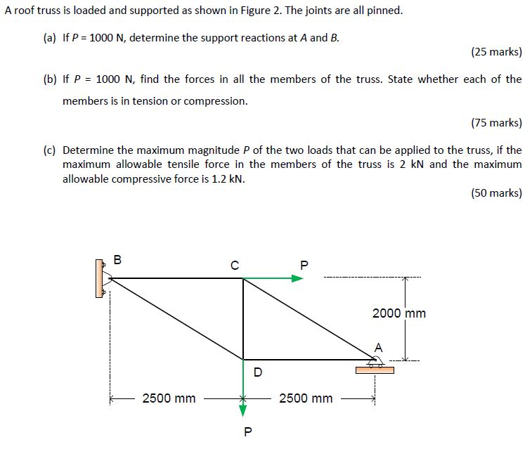
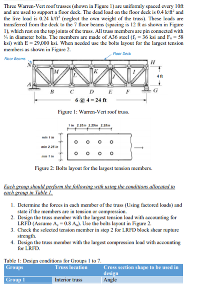
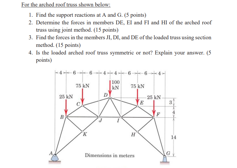
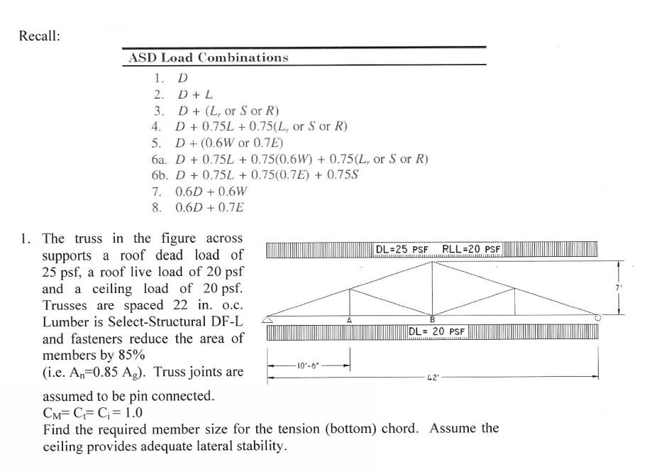
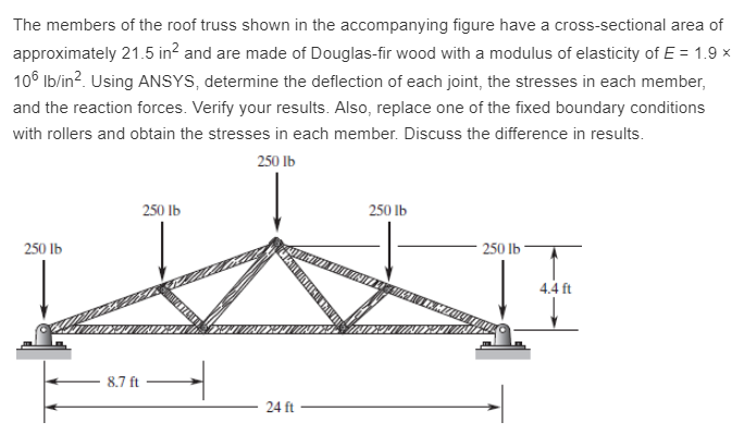
Finding roof loading on a truss at joints chegg. Neglect any horizontal reactions at the supports and assume all members are in tension. Fasteners do not reduce the area off the members. 3 determine the loads on the roof truss based on the tributary area and the load path. The reaction at eis p f1 f1 f1 f1 b в 2 m 2 m h 2 m g 2 m f 2 m select one.
For f1 8 6 and p 17 2. 39 2 the internal force in member ef. The truss in fig. 25 8 o b 5 7 o c.
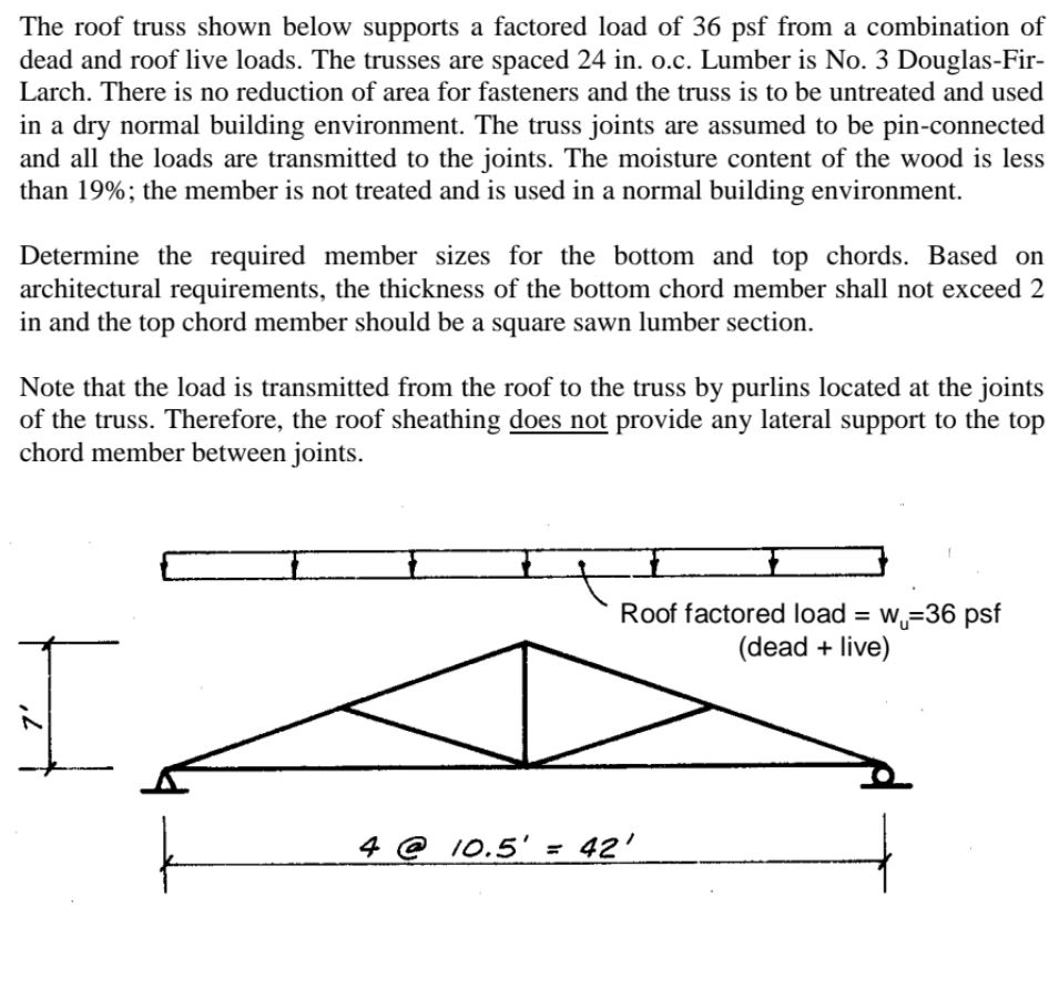
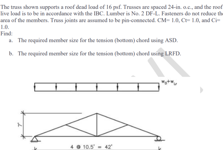
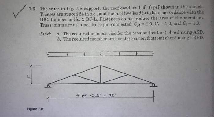
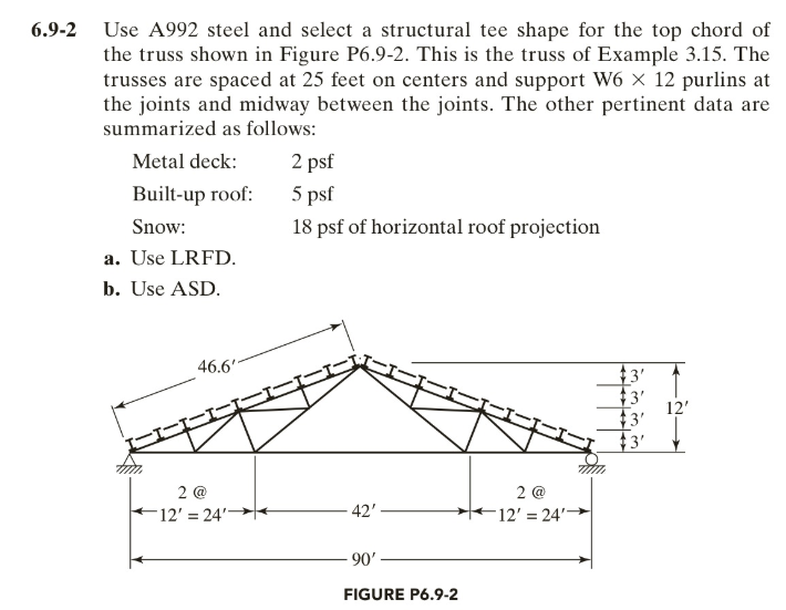
The truss is to be designed using seasoned f22 grade jarrah timber. 4 determine the external reactions. Truss joints are assumed to be pin connected. Trusses are spaced 24 in o c and the roof live load is to be in accordance with the ibc.
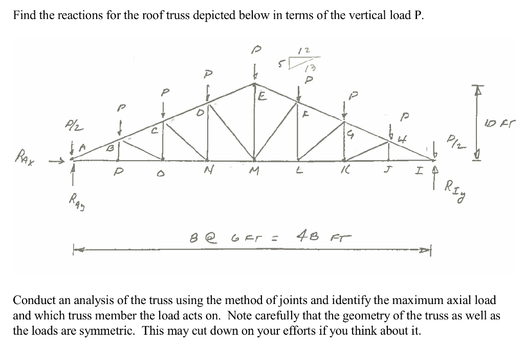
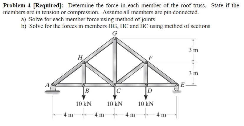
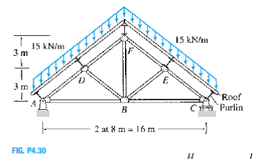
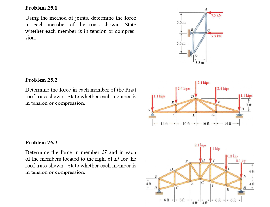
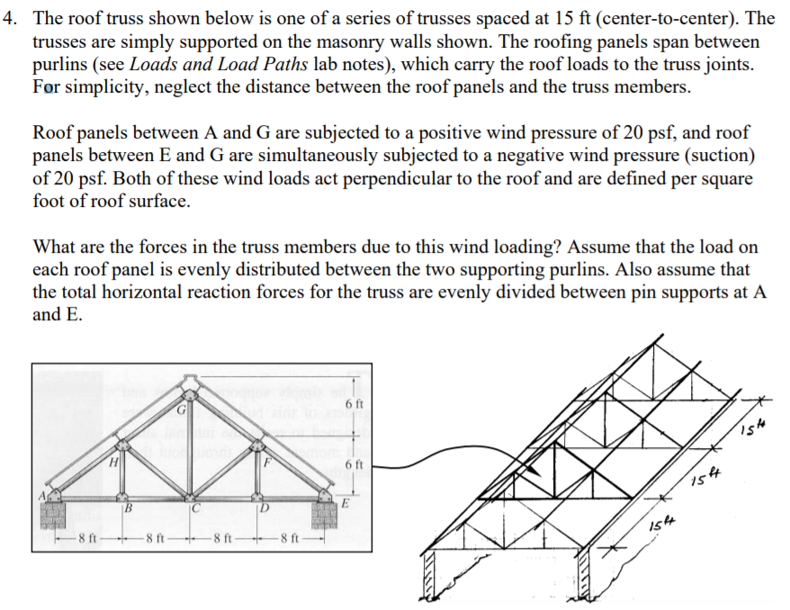
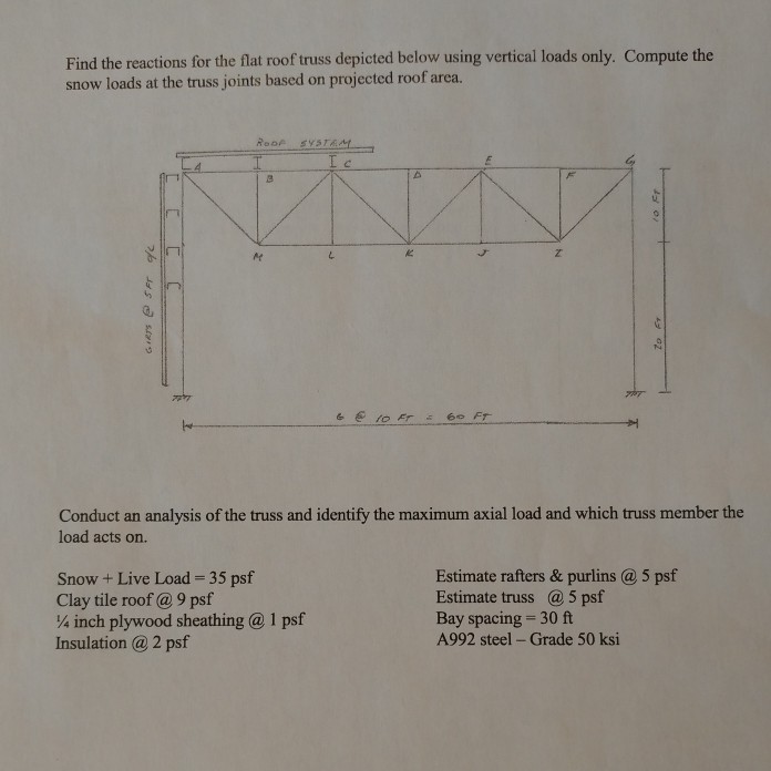
The roof truss shown is one of a series of trusses spaced 16 ft center to center. State whether each member is in tension or compression. 7 b supports a roof dead load of 16psf. For simplicity neglect the distance between the roof panels and the truss members.
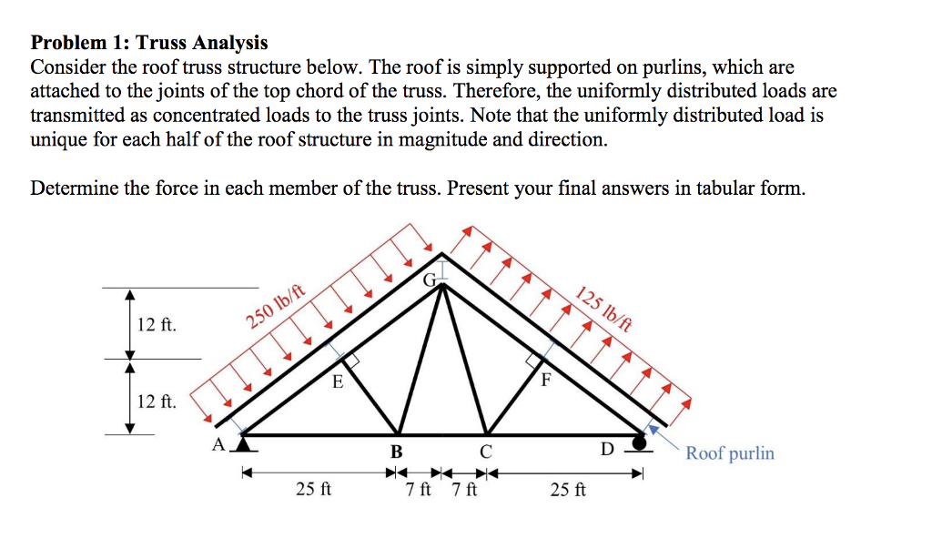
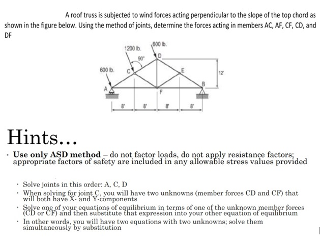
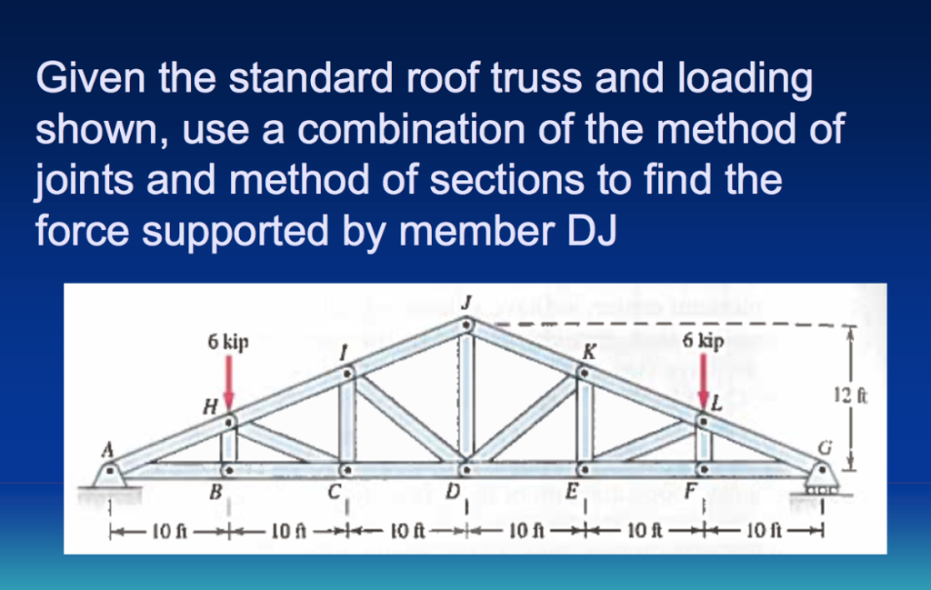
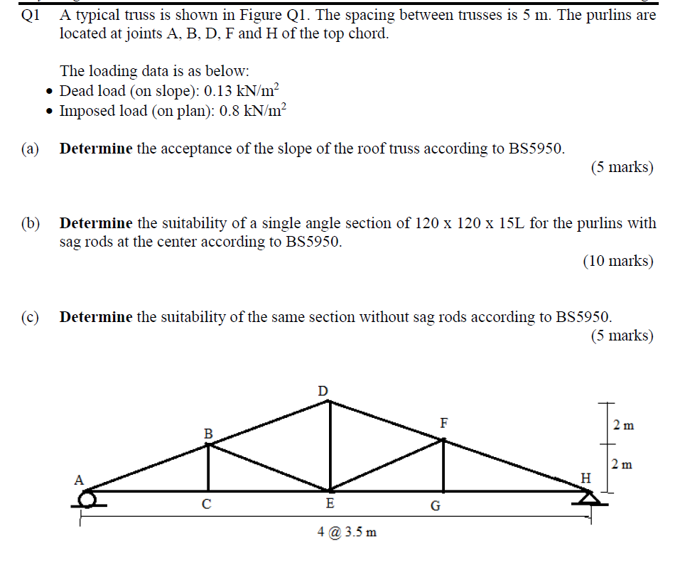
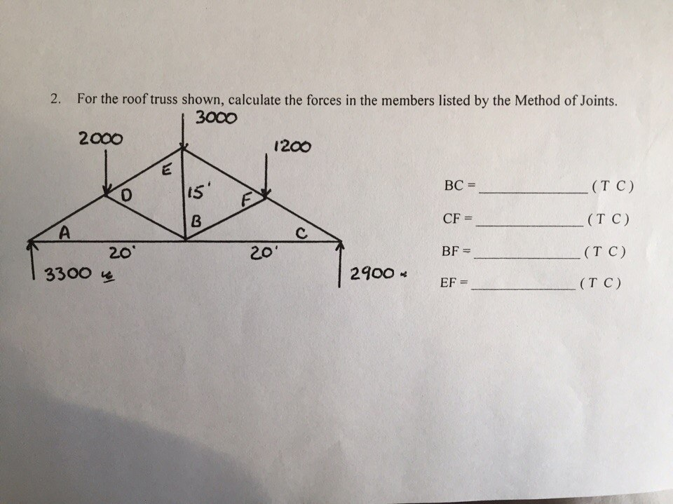
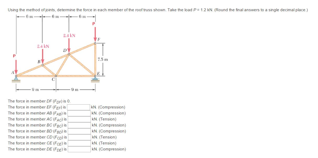
2 what type of load is acting on the roof truss shown in the figure roof self weight snow or wind. The roof is simply supported on purlins which in turn are attached to the joints at the top chord of the truss. Use the method of joints for both numbers to determine the force in each member of the roof truss shown. The roofing panels span between purlins see loads and load paths lab notes which carry the roof loads to the truss joints.
